As the first stage of my senior design project, I built a small battlebot over the course of a semester with a small team. The project developed skills in integration, electronics, mechanical design, and material selection.
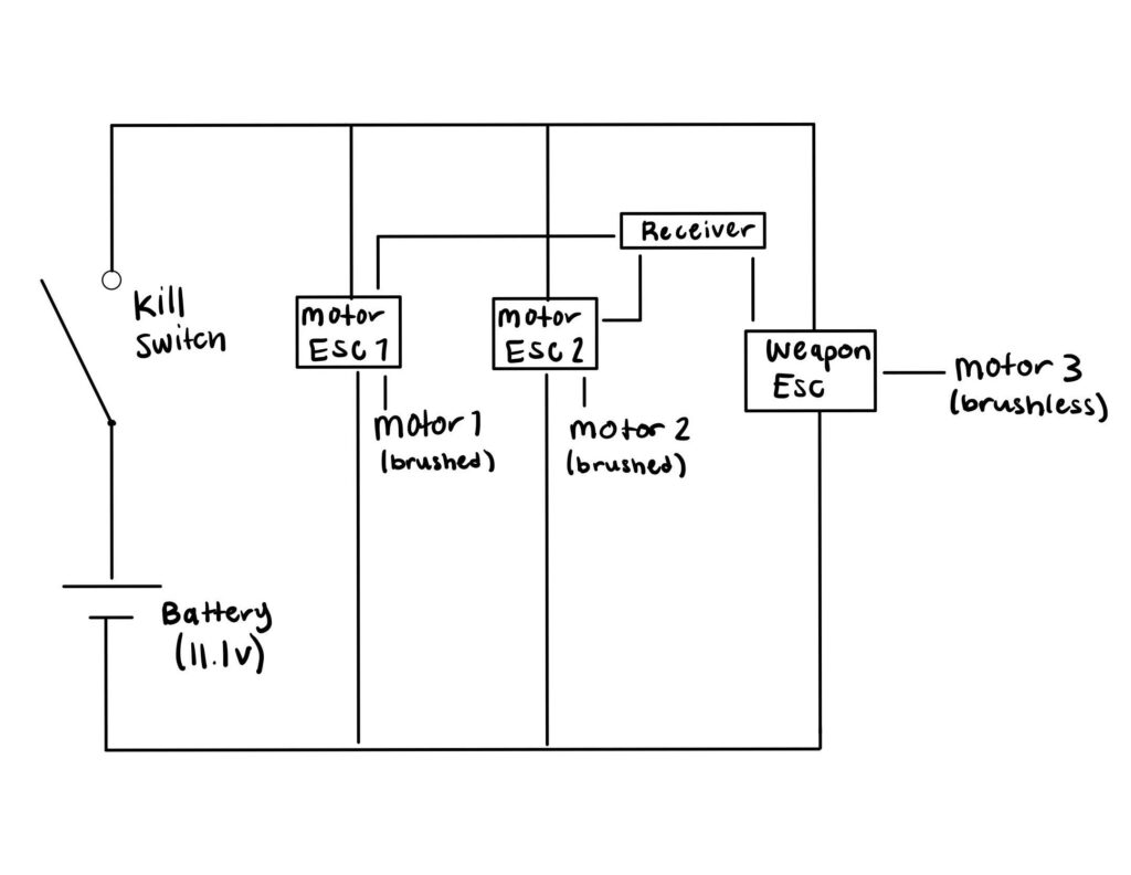
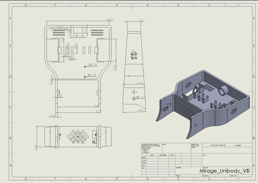
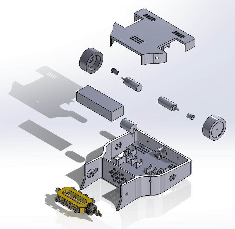
The diagrams above display critical stages of the design cycle, the electrical system and the chassis. It was designed as a two-wheel, differential-drive robot with a brushless motor driving a belt spinning a metal bar for combat.
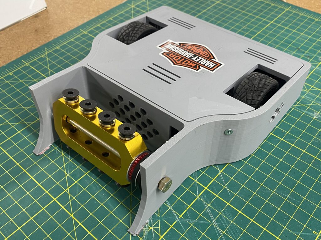
The chassis was designed in two sections, a main body and a top panel. This design enabled the entire chassis to be made from only 2 pieces that could be 3D printed in PLA.
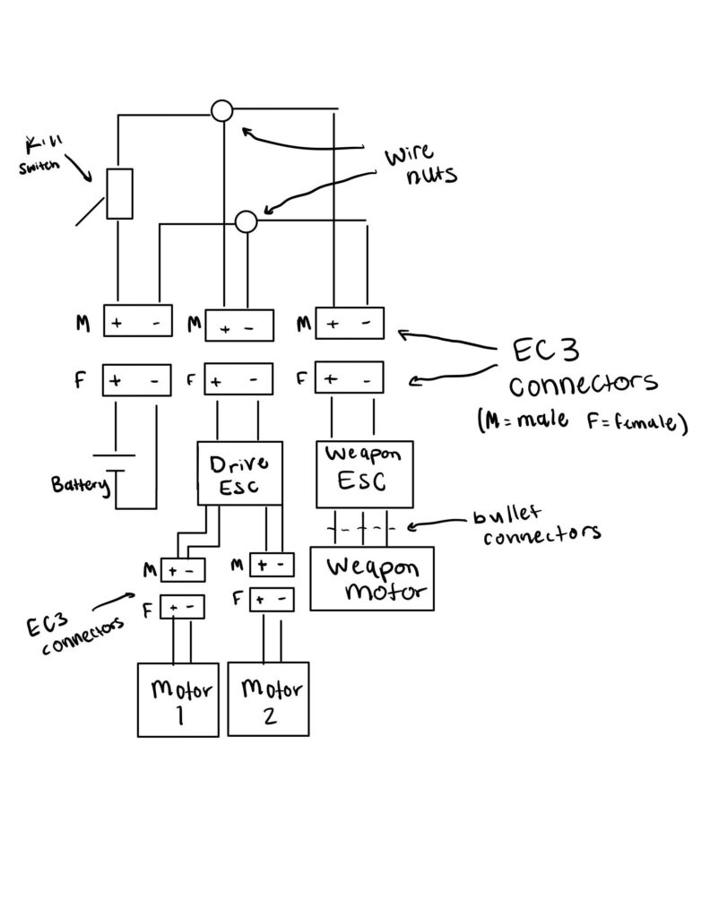
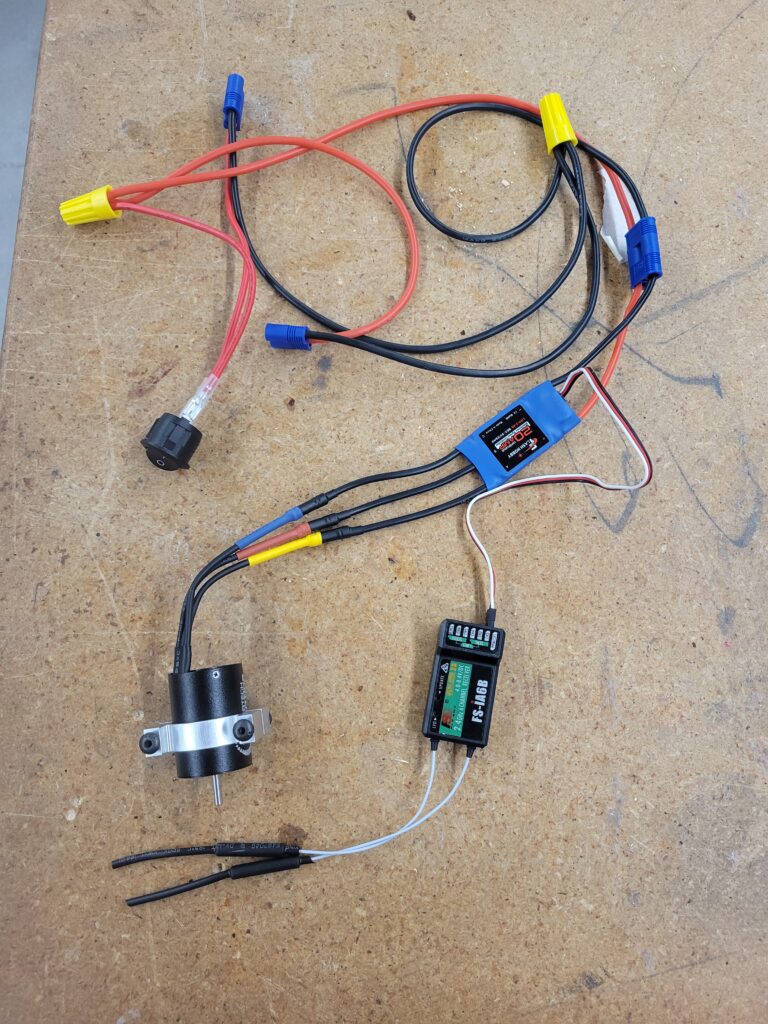
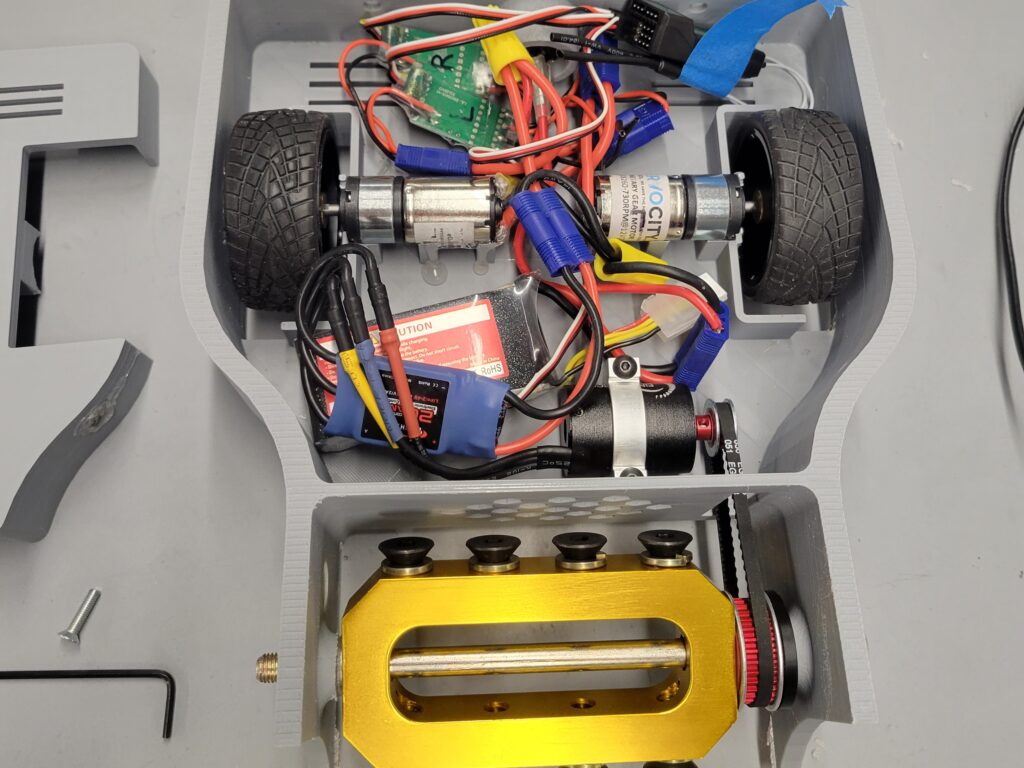
The diagram on the left shows the wiring diagram and the picture on the right shows the constructed wiring harness.
Key electrical components were a disconnect (kill) switch, RC receiver, 1 brushless motor ESC, and 2 brushed motor ESCs all powered by a 11.1V LiPo battery.