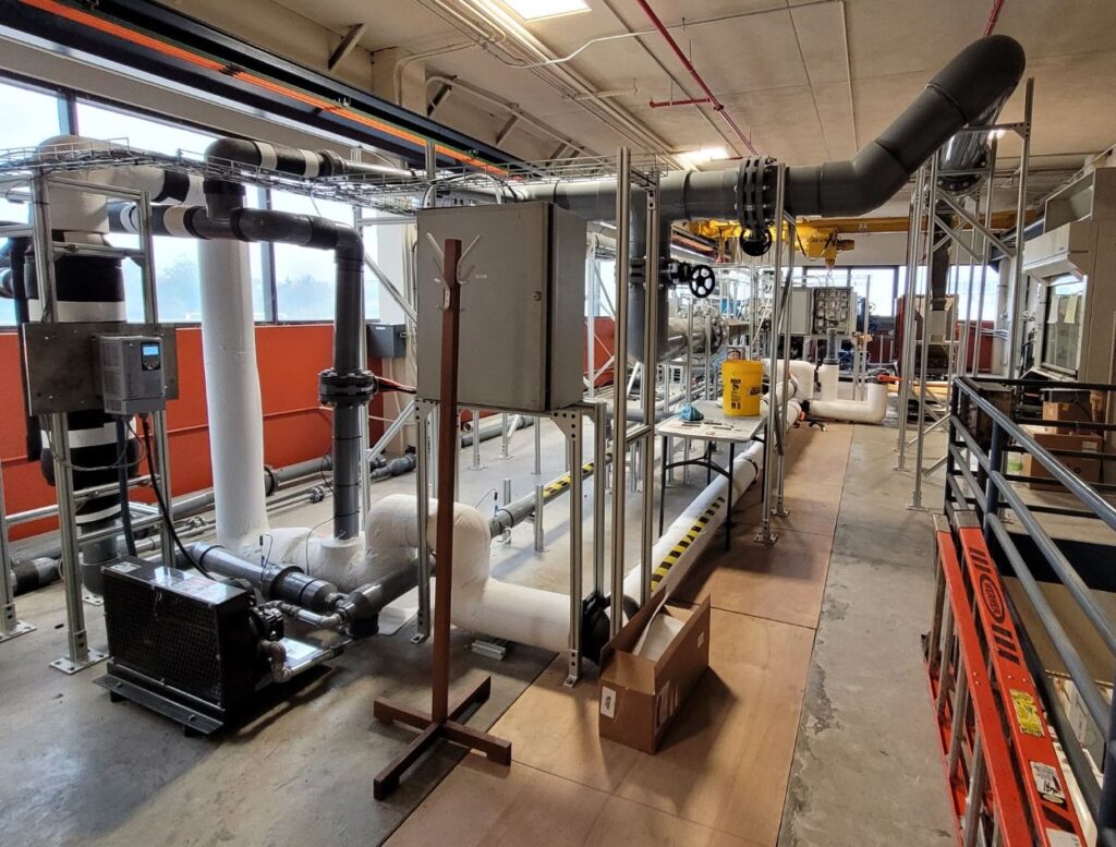
High Speed Wind Tunnel Facility at J.J. Pickle Research Campus
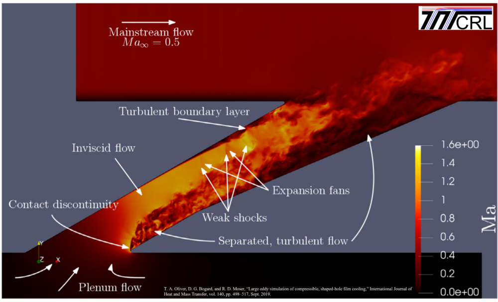
Recent work shows it is critical to match engine realistic Mach numbers (0.5 to 0.8) to quantify the film cooling performance of shaped film cooling holes. Shaped holes have peak performance at high coolant flow rates for which the coolant velocity exceeds the mainstream velocity. At such high flow rates and when Mach number is matched, compressible flow effects dominate the in-hole physics, resulting in significant performance degradation. These findings challenge the decades-old convention of low-speed testing and necessitate testing at engine realistic Mach numbers to accurately predict performance.
The transonic wind tunnel facility is a new addition to TTCRL, having been fully constructed in Spring 2022. Located at J.J. Pickle Research Campus, this facility is a continuous closed-loop wind tunnel consisting of two separate test sections: a simplified flat plate with and an airfoil test section mimicking a linear cascade. Engine realistic Mach numbers and Reynolds numbers are matched, and coolant-to-mainstream density ratios ranging from DR = 1.2 – 2.0 are achieved through use of cryogenic air as the coolant supply.
Summary of facility capabilities:
- IR thermography
- Boundary layer measurements (hot-wire anemometry, Preston tube)
- Wake pressure loss measurements
Flat-Plate Turbine Film Cooling Test Facility
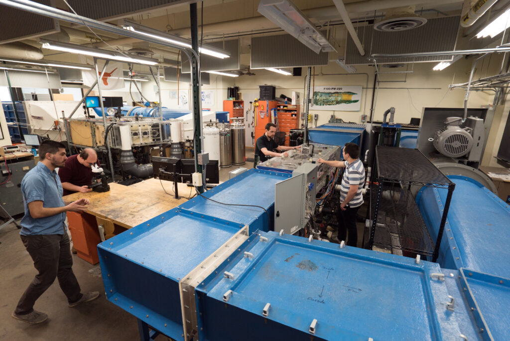
This facility is designed primarily to test different film cooling hole configurations. Test models of film cooling holes are built with additive manufacturing processes, typically at 10X scale. IR cameras are used to measure surface temperatures and processed to determine adiabatic effectiveness or heat transfer coefficient. Detailed measurements of the mean and turbulence velocity fields are measured using hot-wire anemometer, LDV (laser doppler velocimeter), and PIV (particle image velocimeter) systems.
Turbine Airfoil Test Facility

Various turbine blade and vane models are installed in this test facility for measurements of adiabatic effectiveness (low conductivity models), overall cooling effectiveness (matched Biot number models), heat transfer coefficients, thermal fields, and velocity fields. This measurements provide comprehensive performance evaluation and understanding of fundamental physical mechanism for effective cooling of turbine airfoil. The facility operates at realistic Reynolds numbers and mainstream turbulence conditions. For film cooling studies, a cryogenic secondary cooling system is used to provide simulated turbine coolant air at absolute temperatures that are half of that of the mainstream.