This facility operates up to 10 atm to test the effects of elevated pressure on combustion systems. Our current use is to investigate flame flashback in swirl flames and equivalence-ratio stratification. The facility is approximately 8 inches in diameter and constructed from stainless steel for strength and to avoid corrosion.
The High-Pressure Combustion Facility is designed to accommodate burners that generate up to 300 kW of thermal power. The heat is managed by using a co-flow of cool dilution air that surrounds the flame, and additional dilution air in the exhaust section. A heat exchanger in the exhaust further cools the flow. High-pressure air is provided by the Mach 5 wind tunnel’s air supply system. The test-section pressure is maintained by a back-pressure regulator located approximately 20 feet downstream of the combustor.
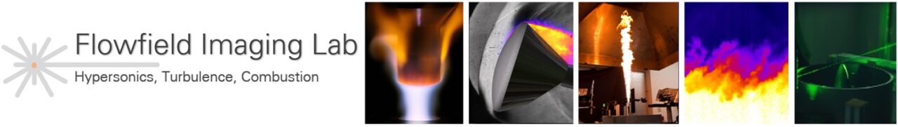
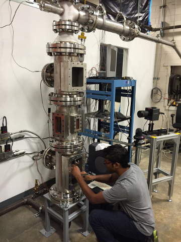
The facility is shown in the photos below. The burner is placed inside the test section and the burner itself need not be a pressure vessel. The test section is the section with the rectangular window in the top photo. Two rectangular access ports allow for manual access to the internal assembly upon which the burner is mounted. The middle photo shows a student accessing the burner access port, which is above the test section. The test section provides the primary optical access to the burner. Optical access is provided by three UV-grade fused silica rectangular windows, two of dimensions 6 in by 2.4 in, and a smaller one of dimensions 4 in by1.5 in. Cameras configured for stereoscopic PIV are shown in the bottom photo.
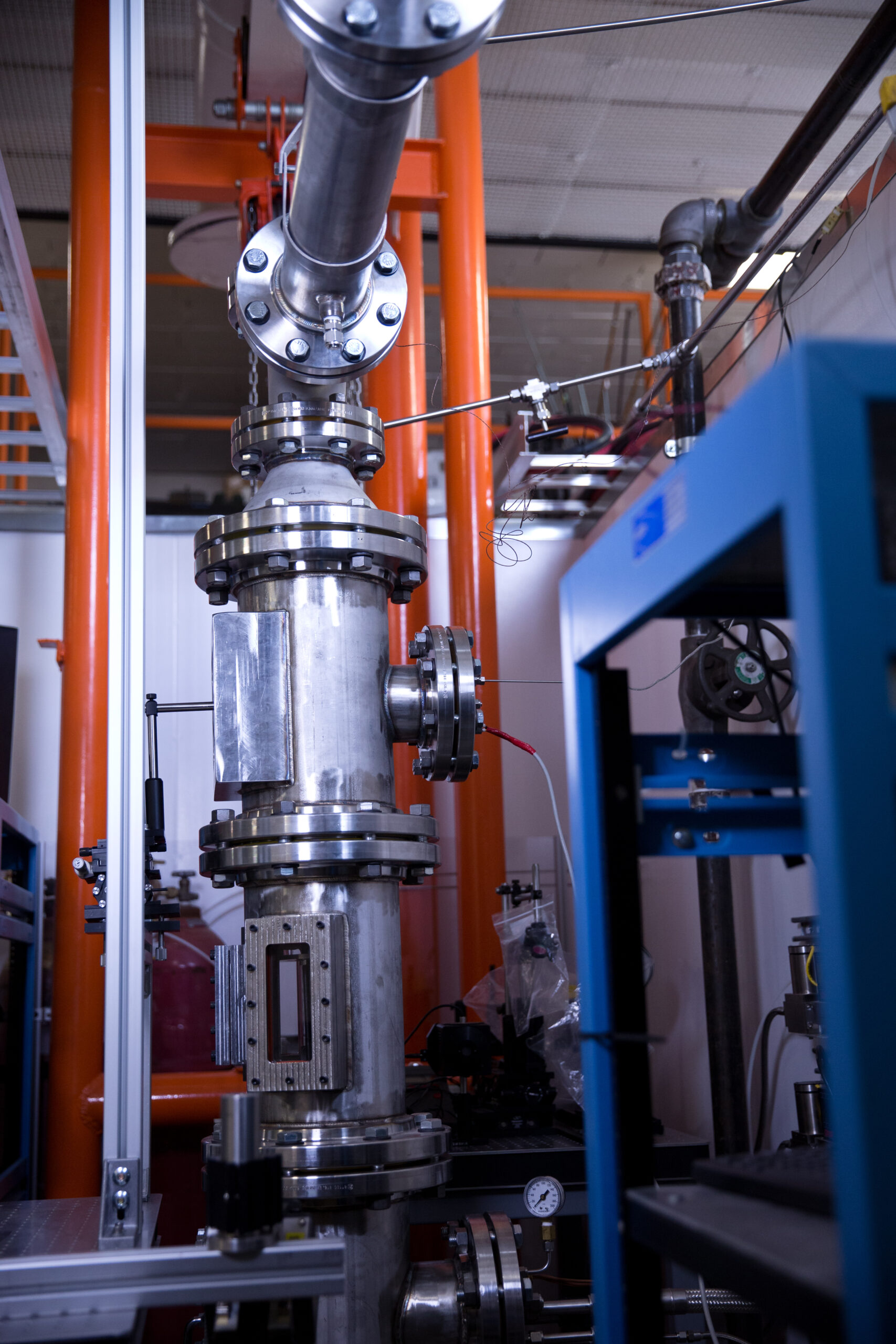
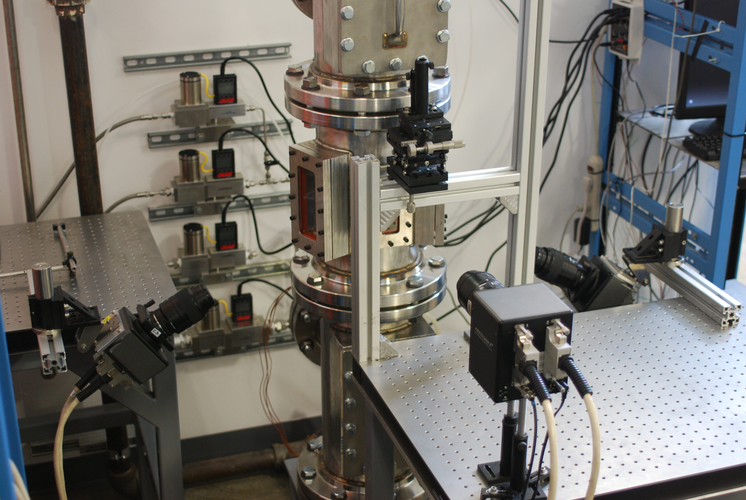
Photos of the High-Pressure Combustion Facility. Test section (with rectangular window) and burner access section (top); student setting up calibration target through the burner access port (middle); stereo PIV setup (bottom)