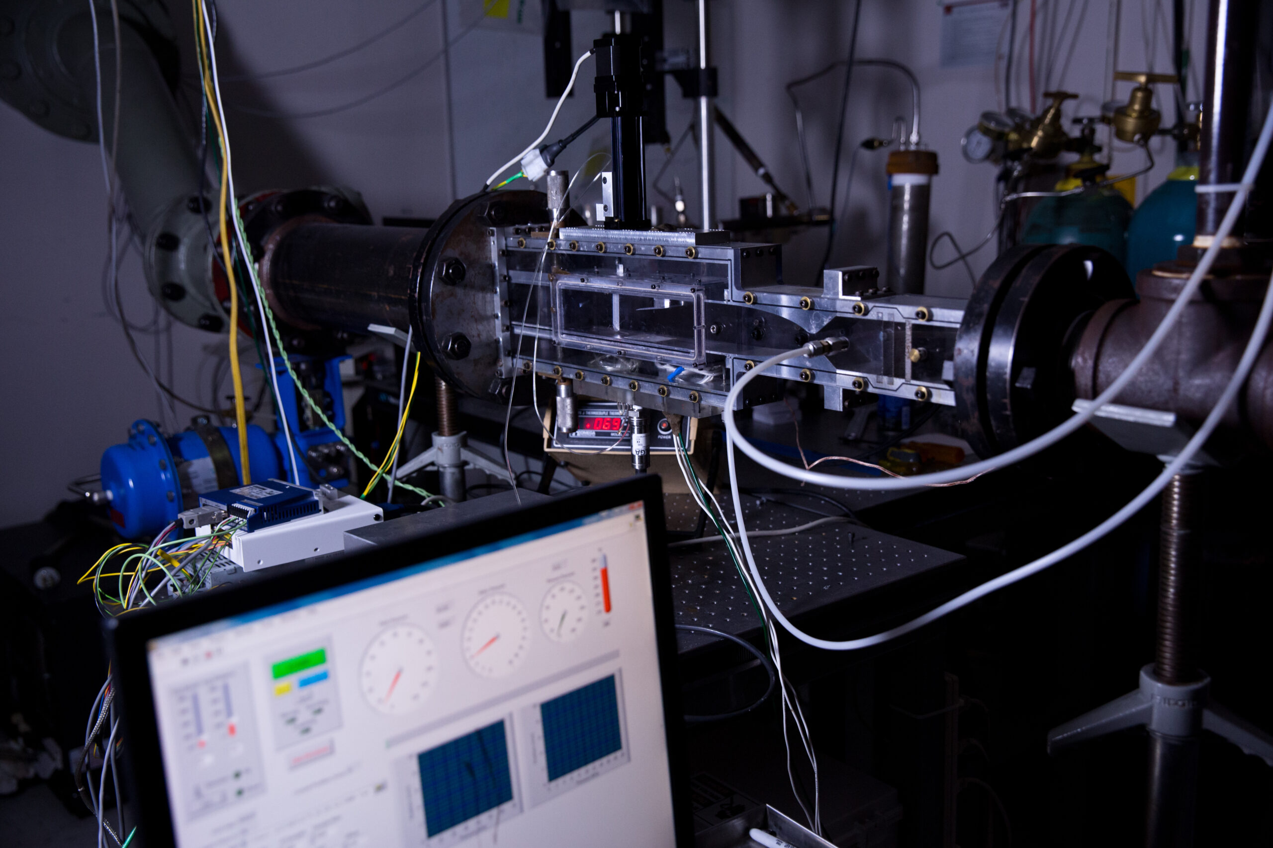
The Mach 3 wind tunnel facility is a smaller-scale, low-Reynolds number tunnel with a 2 inch by 2 inch test section. The tunnel operates on air or nitrogen and is driven by a pressure-vacuum system with run times of about 1 minute. The facility is manufactured largely of acrylic as it has been used extensively for plasma actuator development.
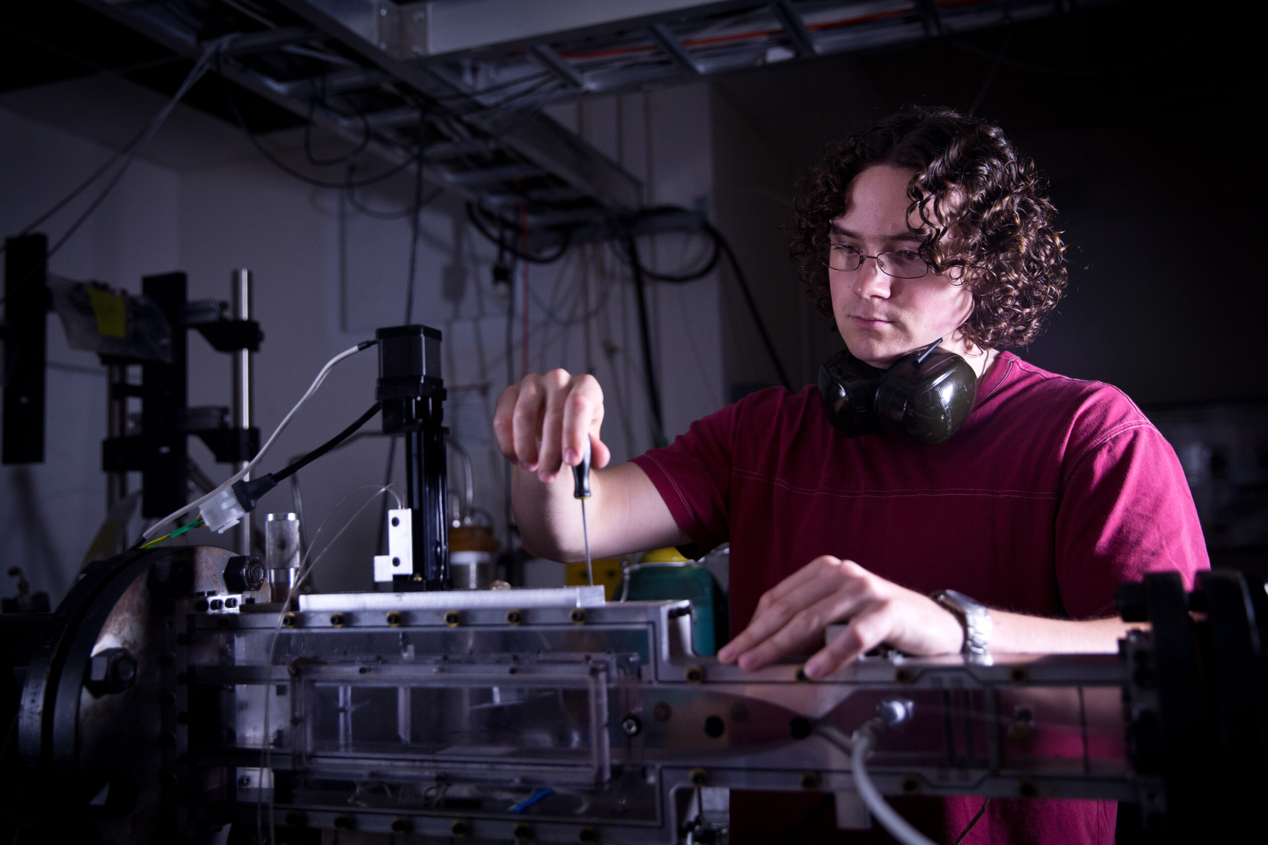
Photos of the Mach 3 wind tunnel. (top) Tunnel showing transparent test section, exhaust valve, and exhaust piping; (bottom) test section and student pretending to work.
The air is supplied by an upstream 200 psi storage tank, which is throttled upstream of the plenum to 1 to 2 atm. The facility exhausts to a 50 cubic meter vacuum, which is evacuated in about 45 minutes to a few Torr by a Roots blower. The tunnel is shown in the figure below. The Mach 3 nozzle block and test-section internal upper and lower walls are made of aluminum, but the sidewalls are made of acrylic.
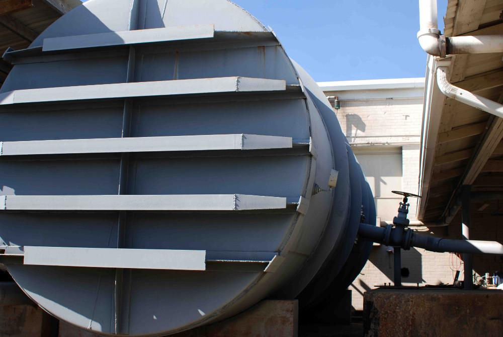
Photo of the Mach 3 tunnel vacuum tank
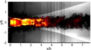
Owing to its small size, low-pressure operation and thus relatively low mass flow rates, it has been used extensively for the development of diagnostic techniques and plasma actuators. For example, the figure below by Eric Lachney (Lachney, E.R. and Clemens, N.T., “PLIF Imaging of Mean Temperature and Pressure in a Supersonic Bluff Wake,” Experiments in Fluids, Vol. 24, No. 4, pp. 354 – 363, 1998) represents imaging of the pressure and temperature fields in a supersonic wake. These images were obtained by seeding the main flow with trace levels of nitric oxide and performing planar laser-induced fluorescence imaging. When the NO was seeded into nitrogen it was not quenched and so it was sensitive to pressure. The temperature was derived by pumping two different absorption lines of NO and taking the ratio of the fluorescence signals; the ratio was then related to temperature using theoretical relations.
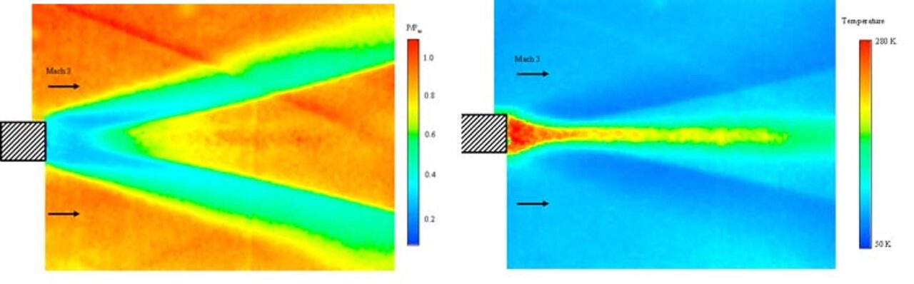
Mean pressure (left) and temperature (right) imaging of a Mach 3 turbulent wake by NO PLIF.
The Mach 3 tunnel has also been used for studies of pulsed plasma jet actuators and their application to the control of shock wave / boundary layer interactions. Sample results are shown in the figure below, where a long-exposure photo of an array of three plasma jets is shown at top, and an animated gif of the response of the separation shock to the plasma jets is shown at bottom. These studies are reported in the following papers:
Narayanaswamy, V., Raja, L.L. and Clemens, N.T., “Control of Unsteadiness of a Shock Wave / Turbulent Boundary layer Interaction by using a Pulsed-Plasma Jet Actuator,” Physics of Fluids, Vol. 24, pg. 076101 (22 pages), 2012.
Narayanaswamy, V., Raja, L.L. and Clemens, N.T., “Method for acquiring pressure measurements in presence of plasma-induced interference for supersonic flow control applications,“ Measurement Science and Technology, Vol. 22, 125107 (11 pages), 2011.
Narayanaswamy, V., Raja, L.L. and Clemens, N.T., “Control of a shock/ boundary layer interaction by using a pulsed-plasma jet actuator,” AIAA Journal, Vol. 50, No. 1, pp. 246-249, 2012.
Greene, B.R., Clemens, N.T., Magari, P. and Micka, D., “Control of Mean Separation in Shock Boundary Layer Interaction Using Pulsed Plasma Jets,” Shock Waves, Vol. 25, Issue 5, pp. 495-505, 2015.
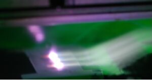
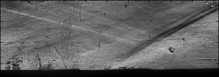
Long-duration photo of a pulsed plasma jet array (top); Phase averaged moving of the pulsed-plasma jets interacting with a separation shock upstream of a compression ramp (bottom).
In another study, Ross Burns used krypton planar laser-induced fluorescence to study mixing in a hypermixer configuration. Kr PLIF, which was developed in our laboratory, and is beneficial because krypton is inert and thus does not present a hazard to human health as NO does. The figure below shows that Kr PLIF enables us to conduct high-quality imaging of the mixing process.
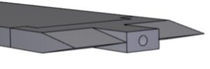
Hypermixer geometry (top); Composite image showing Kr PLIF in yellow-red colormap and planar Mie scattering in grayscale (bottom)