The Chemistry Department’s X-ray facility at The University of Texas at Austin collaborates with other schools and provides training for graduate and undergraduate students.
Are you an undergraduate or graduate student at UT who would like to learn to collect data on your own samples and produce your own crystal structures? Email the lab manager, Serhii, to set up a meeting to get started.
Collaborations & Outreach
X-ray Education
Crystal Lattices and the Unit Cell
Single crystals are necessary for determining the three-dimensional structure of a metal-containing compound. The majority of the compounds made in this research stream will contain a lanthanide or a combination of a lanthanide and a transition metal. In order to publish the structures of new compounds, it is necessary to understand why crystals are so important and why time and resources are spent on obtaining X-ray quality crystals.
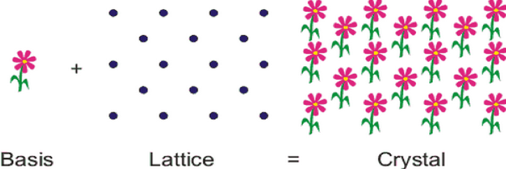
Crystals are solids composed of ions, atoms, or molecules arranged in repeating three-dimensional patterns called unit cells (Figure 1). A unit cell is the most basic and least volume consuming repeating structure of a molecule. It is used to visually simplify the crystalline patterns atoms arrange themselves in. When the unit cell repeats itself, the network is called a lattice. As long as the structure is repetitive, its structure may be discovered with the application of X-ray diffraction.
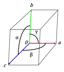
The unit cell has a number of shapes, depending on the angles between the cell edges and the relative lengths of the edges. It is the basic building block of a crystal with a special arrangement of atoms. The unit cell of a crystal can be completely specified by three vectors (a, b, and c) that form the edges of a parallelepiped. The inter-vector angles (a, b, and g) are used to characterize the cell (Figure 2).
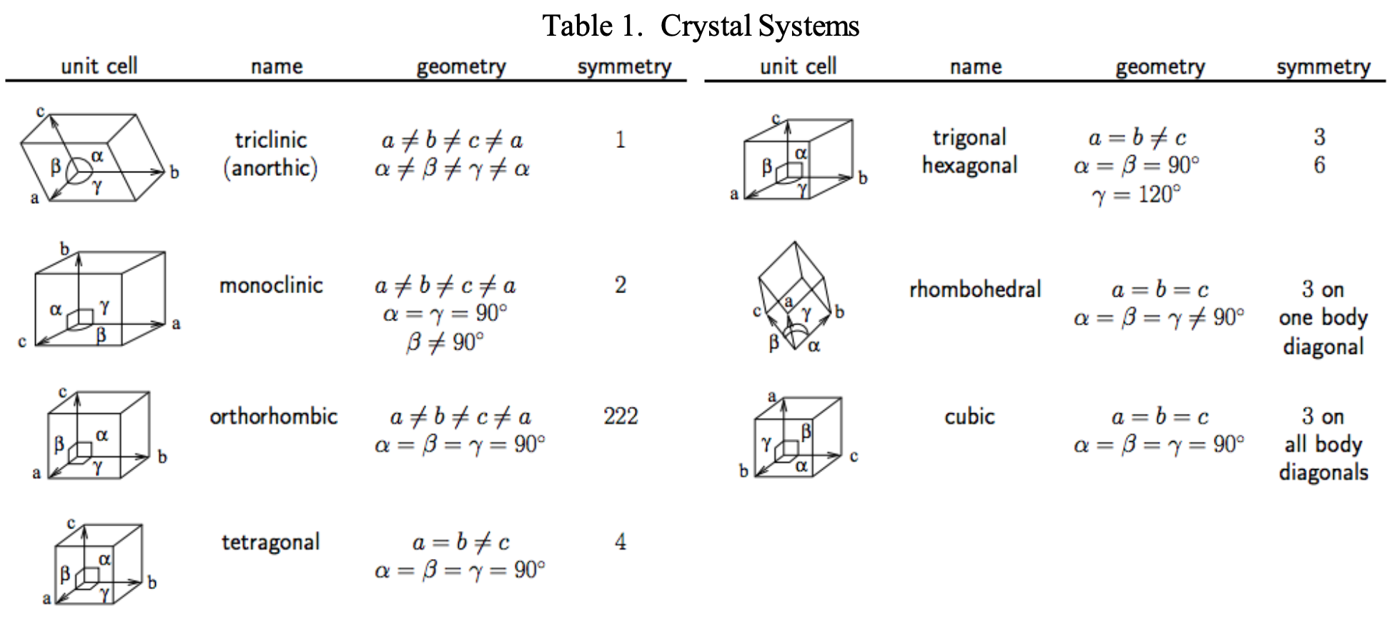
Crystals are never the same cubic shape so a crystal system of 7 classes which determine the type of symmetry elements relating the asymmetric units in the cell. The unit cell shape, name and geometry are shown in Table 1.
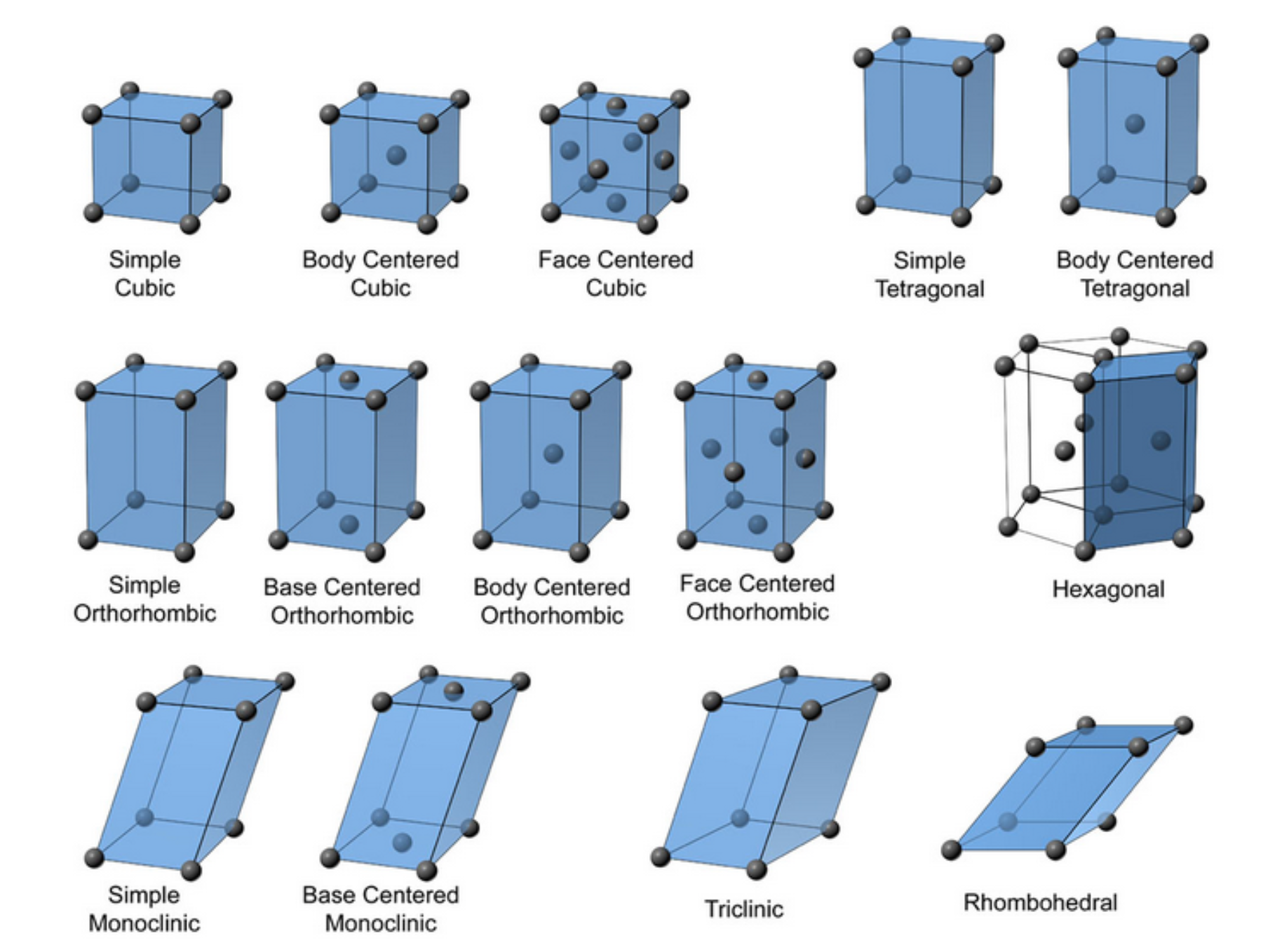
Within the seven crystal systems the placement of atoms can further define the unit cell in the arrangement. This classification includes Simple, Body Centered, Base Centered, or Face Centered. There are a total of 14 types of unit cells known and all crystals can be described as belonging to one or another of these types (Figure 3).
Single Crystal X-ray Crystallography
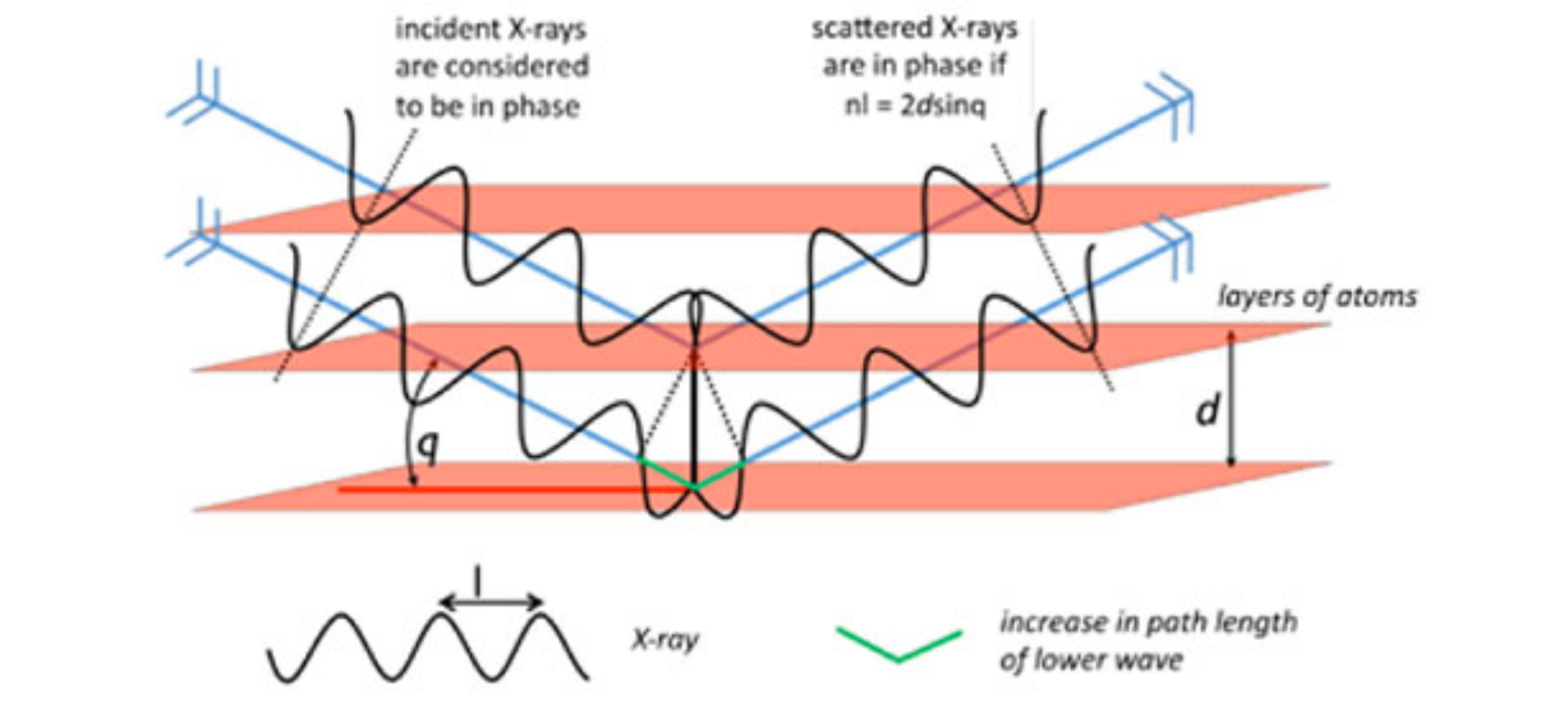
The structures of crystals are identified using X-ray diffraction studies, which are explained by Bragg’s Law. The law explains the relationship between an X-ray beam and its reflection from a crystal surface (Equation 1). Bragg’s Law was introduced by Sir W. H. Bragg and his son Sir W. L. Bragg, who both received the Nobel Prize for Physics in 1915. Lawrence Bragg, the son, is the youngest Nobel Laureate, having received the award at age 25.

Bragg’s Law states that when the X-ray is incident onto a crystal surface, its angle of incidence, q, will reflect back with a same angle of scattering, q. When the path difference, d, is equal to a whole number, n, of wavelength, a constructive interference will occur (Figure 4).
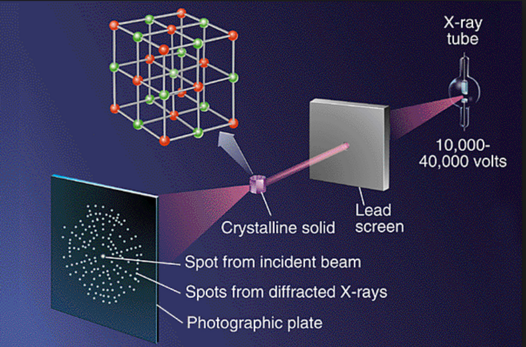
X-rays are directed at the crystal. Rays are either transmitted through the crystal, reflected off the surface, or diffracted by the crystal lattice. Reflected rays are not picked up by the detector due to the angles involved. The detector then collects diffracted rays at the correct orientation for the configuration. Crystals contain several thousand unique reflections, whose spatial arrangement is referred to as a diffraction pattern (Figure 5). Indices (hkl) may be assigned to each reflection, indicating its position within the diffraction pattern. This pattern has a reciprocal Fourier transform relationship to the crystalline lattice and the unit cell in real space. This step is referred to as the solution of the crystal structure. After the structure is solved, it is further refined using least-squares techniques.
Techniques for Growing Crystals
A crystal structure is only as good as the crystal used for data collection. Therefore it is worthwhile spending time on improving the quality of your crystals. Even though growing crystals is more of an art than a science and luck is a major factor, there are some things to do and some other things not to do.
Solubility is the single largest and most used property needed to grow a single crystal. Generally one knows a fair amount of this from the synthesis and other aspects of working with the compound. Stability and reactivity need to be considered. One does not want to cause a reaction with the compound of interest in the solvent system that you are trying to grow the crystals.
Crystallization is preceded by nucleation, which happens either spontaneously or is induced by vibration or particles. If nucleation sets in too quickly, many crystals will grow that are too small. For a diffraction experiment you need no more than one good single crystal. The best way of growing a few nice crystals, when opposed to a lot of bad crystals, is to change the concentration slowly into the area of nucleation, without getting too deep into it. The formation of nuclei (not too many) and the starting crystallization will reduce the concentration and bring the solution back into the region of oversaturation. That is where existing crystals grow, but no new nuclei form. You want to keep your system there. That means all changes of your system need to be slow.
Once you have crystals, never remove the solvent! Frequently, solvent molecules co-crystallize with the compound, which makes them integral parts of the crystal lattice. Removing the mother liquor from the crystals exposes the crystals to air and the volatile solvent molecules slowly evaporate from the crystal lattice, leaving empty holes. Very small holes reduce the maximum resolution the crystal diffracts to; larger holes destroy the crystal. It is always a good idea to not change the environmental conditions for your crystals too often. Leave them alone, when you can.
Diffraction quality crystals need to be relatively large. Maybe not quite on the engagement ring scale, but 0.1 to 0.3 mm in each dimension is a good number. In order to grow large crystals, it is important to avoid having to many nucleation sites. Crystals that grow more slowly, tend to be larger. Five main methods are described below for the crystallization of compounds. All will work with organic and inorganic compounds.
- Evaporation
This is the most common methodology for crystal growth, and involves simply evaporating solvent from the solution of the compound until saturation is reached and crystals form. This method is not the best and often leads to ugly crystals since the crystals tend to grow on the surface of the vessel.
- Slow Cooling
This is the most standard method of recrystallization and it works well by following the solubility rule of “soluble hot, insoluble cold”. We want to have crystals form very slowly; slow reduction of temperature works the best. Most often you will put the solution to grow crystals in the fridge or freezer. To reduce the time for the vial and solvent system to cool, one can place the vial of solution into another container (Styrofoam box, jar with lid, etc.). Any solvent is fair game for this method (with the exception of water and benzene in the freezer). Simply make a saturated solution of the compound and allow it to cool, usually by placing the solution in the freezer.
- Sublimation
If you’re very fortunate, your compound may be sufficiently volatile for this technique. Simply heat the compound (generally under vacuum), and collect crystals on a cooled cold-finger. Often the collected material is highly crystalline, and, best of all, by the very nature of the method free of all solvent impurities. Sublimation should not be the method of choice to grow diffraction quality crystals. Sublimation usually takes place at relatively high temperatures, which means that there is to a lot of energy in the system when the crystals form. At high temperature the differences between two similar molecule orientations can become insignificant which results in a twinned or statically disordered crystal. In addition, crystals are usually growing too fast when they are obtained by sublimation, which can also facilitate twining or disorder.
- Slow Vapor Diffusion
For this method you need a binary solvent system. Choose two liquids that mix well. Your compound should be soluble relatively well in the liquid with the higher boiling point (solvent 1), and as good as insoluble in the liquid with the lower boiling point (solvent 2). Prepare a solution of your compound in a small open container (we use test tubes). Place this receptacle inside a larger one that contains some precipitant and seal the outer vessel well (glass jar with blue lid). Over time the precipitant, which is more volatile, will diffuse over in the gas phase into the solvent, leading to oversaturation, nucleation and, if all goes well, finally crystallization.
- Liquid-Liquid Diffusion
As with the vapor diffusion method, you need a binary solvent system. In this case the boiling points don’t matter very much but the specific densities of the two liquids need to be different. The two solvents need also to be miscible (see miscibility Table 2 on next page). Prepare a concentrated solution of you compound in the solvent and have the precipitant handy. Transfer a small volume of whichever liquid has the higher specific density in a narrow receptacle and carefully layer it with the other liquid. Over time the two solvents will mix and, if you are lucky, crystals will form. A variation of this method is to freeze the lower layer before you add the second liquid. That makes it much easier to get a clean separation between the two layers.
Structural Determination
While there are many ways to solve and refine or work up the data collected by the instruments, students are taught the program called Olex2. Applicable to Mac and Linux platforms as well as Windows PC’s. Olex2 has a nice graphics interface.
To download and use Olex2, follow the Notes produced by Ilia A. Guzei: http://xray.chem.wisc.edu/Resources/Manuals/Ilia_Guzei_notes_on_OLEX2.pdf
You will need to register for OlexSys before downloading: http://www.olexsys.org/Software
You will also need programs SHELXT and SHELXL (written by George Sheldrick) available free upon request (you will also need to register for these) from: http://shelx.uni-ac.gwdg.de/SHELX/
Another useful program is PLATON (http://www.platonsoft.nl/platon/). PLATON contains many useful features for problem solving for difficult structures. It is an essential tool for all crystallographers.
CHECKCIF – An online program that will check your cif file for potential problems (http://checkcif.iucr.org/). The results will list a series of Alerts that can be addressed before final submission. It can generate a checkcif results file in pdf format for submission to journals for publication.
Northwestern University has a stellar guide for Structure Solution and Refinement with Olex2: http://imserc.facilities.northwestern.edu/files/2013/11/Olex2atNUv1.1.pdf